|
What you must
specify when selecting solenoid valves
●
Type of valve required (solenoid or pressure actuated)
●
Body and valve internal material(s)
●
Fluid flowing through the valve
●
Line pressure at the valve and allowable pressure drop (pilot operated
or force lifting principle)
●
Nominal diameter required (matching process line size or from flow
calculations)
●
Connection (NPT, G or flange)
●
Fluid temperature
●
Ambient temperature
●
Switching function (normally-open or normally-closed)
●
Available electrical power
●
Protection classification (IP rating and explosion-proof)
----------------------------------------------------------------------------------------------------------------------------------------------------
Actuation and Valve Types
The valves shown in this
catalogue are designed to control (on/off) the flow of fluids by the aid
of a solenoid or pressure actuation. They are divided into two major
categories: (1) Solenoid Valves and (2) Pressure Actuated Valves. A
solenoid valve consists of a valve and a solenoid (electro-magnet) which
controls the valve. A pressure actuated valve, in this catalogue, is an
angle seat valve with a pressure actuated system on top, to control the
valve.
VALVE TYPES
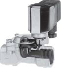
Diaphragm Valves
|
● Suitable for maximum operating pressure of 230 psi (16 bar)
|
 |
|
● Suitable for maximum viscosity of 25 cst |
|
● Good for operations with or without differential pressure |
|
● Valve body made from stainless steel or brass
|
|
● Connection sizes between ¼" and 2", NPT and G
|
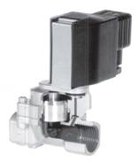
Piston Valves
|
● Suitable for maximum operating pressure of 600 psi (40 bar) |
 |
|
● Suitable for maximum viscosity of 150 cst |
|
● Can be used for fluids up to +200ºC temperature
|
|
● Good for operations with or without differential pressure |
|
● Valve body made from stainless steel or brass |
|
● Connection sizes between ¼" and 2", NPT and G |
|
● Damped operation standard |
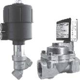
Pressure Actuated Valves
|
● Suitable for contaminated and very viscous fluids
|
 |
|
●
Can be used for fluids up to +180ºC temperature
|
|
●
Low closing shock is the result of fluid flowing
against the valve plate |
|
● Valve body made from stainless steel, cast iron, cast steel or
gunmetal |
|
● Connection sizes between ¼" and 2", NPT and G |
----------------------------------------------------------------------------------------------------------------------------------------------------
Line Pressure and
Pressure Drop
Fluid pressure at the valve inlet and allowable pressure drop are very
important parameters for selection of the valves. The piston valves are
designed to withstand up to 600 psi (40 bar) pressure, while the
diaphragm valves are suitable for up to 230 psi (16 bar) pressure -see
the data sheets.
Pressure drop across a valve
can be calculated when the valve sizing coefficient (Cv or Kv
) and the flow rate of the fluid along with its specific gravity
and viscosity have been determined. For pressure drop calculations,
please see the flow rate calculations section.
----------------------------------------------------------------------------------------------------------------------------------------------------
Valves with or without
∆P
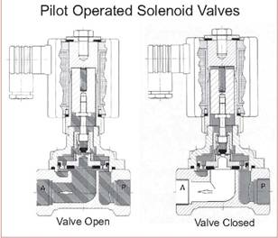
When pressure drop is a concern, Indumart offers two groups of valves.
(1) The pilot operated solenoid valves, which require a minimum
differential pressure for operation, and (2) the force lifting solenoid
valves that do not require a pressure differential to operate.
|
The pilot operated solenoid valves operate on the servo assistance
principle, which requires a specified differential pressure for
opening and closing. These valves have a pilot and bleed orifice
which enables them to use line pressure for operation. In the
normally-closed valves, when the solenoid is de-energized, the pilot
orifice is closed and full line pressure is applied to the top of
the diaphragm or piston through the bleed orifice, providing seating
force for tight closure. Provided the differential pressure between
the inlet and the outlet of the valve be at least equal to or
greater than the required Δp, the valve would remain securely
closed. The valve will only close tightly in the direction of flow.
Flow in the opposite direction to the arrow may damage the valve.
When the solenoid is energized, the pilot seat will open, the
pressure on the main closure device will be relieved, and raised
into the open position by the increasing effective force on the
underside. The line pressure will keep the valve open. |
 |
| |
|
|
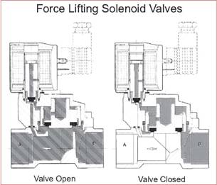
The force lifting solenoid valves are designed for reliable service
in the vacuum and low pressure ranges, where any differential
pressure is insufficient to allow the use of servo assisted solenoid
valves. The force produced by the solenoid plunger, which is
mechanically coupled to the main closure device, opens this type of
valve. The sequence starts with the solenoid opening the pilot
seat. This relieves the pressure on the main closure device,
bringing it into balance so the solenoid force can lift it into the
open position. When the pilot seat is closed, bleed orifices allow a
force to build up on the closure device that pushes it down into the
closed position on the valve seat. |
 |
----------------------------------------------------------------------------------------------------------------------------------------------------
Flow Rate Calculations
Valve models must be carefully selected and
accurately sized to suit the system application. Once the permissible
pressure drop across the valve have been determined, specific gravity
and flow rate of the fluid govern the connection size (non-viscous
fluids).
A basic
sizing equation for liquids can be written as follows: Q(liquids)
= Cv X SQ.RT(∆P/s.g.)
where
Q is the flow rate in U.S. gallon per minute.
Cv is the valve sizing coefficient determined
experimentally, and is defined as the number of U.S. gallons of water at
60°F that will flow through the valve in one minute, when the pressure
differential across the valve is 1 psi.
∆P is the pressure drop at the valve is 1 psi.
"s.g." is the specific gravity of the liquid (s.g. of water at
60°F is 1.0000).
Viscous conditions can result
in significant sizing errors in using the above equation, because the
published Cv values are based on test data using water as the
flow medium. Although the majority of valve applications will
involve fluids where viscosity corrections are relatively small, fluid
viscosity should be considered in each valve selection. By using an
appropriate nomograph, the standard Cv coefficient can
be corrected for viscous applications.
For gases the
equation is: Q(gases) = 16.07Cv
X SQ.RT{[z(p12-p22)]/[Tx(s.g.)]}
(non-critical flow)
where
Q
is the gas flow in SCFM.
Z
is the compressibility
factor.
p1
is the upstream
pressure in psia.
p2
is the
downstream pressure in psia.
T
is the temperature in Rankin scale (°F + 460)
"s.g."
is the specific
gravity of the gas (air = 1)
If the flow coefficient is
given as Kv, the equation will be:
Q(liquids)
= Kv X SQ.RT(∆P/s.g.)
where
Q is the flow rate in m3/h
Kv
is the valve sizing coefficient determined experimentally, and is defied
as the number of cubic meter of water at 15°C
that will flow through the valve in one minute, when the pressure
differential across the valve is 1 bar.
∆P is the pressure drop at the valve is 1 bar.
"s.g."
for water
between 5°C
and 30°C
can be assumed 1.
The flow
coefficient tabulated for each valve allows calculations of parameters
such as flow rate or pressure drop for steady-state flow.
For gases the
equation is: Q(gases) = 341Kv
X SQ.RT{[z(p12-p22)]/[Tx(s.g.)]}
(non-critical flow)
where
Q
is the gas flow in SCMH.
Z
is the compressibility
factor.
p1
is the upstream
pressure in bara.
p2
is the
downstream pressure in bara.
T
is the temperature in Kelvin scale (°C + 273.15)
"s.g."
is the specific
gravity of the gas (air = 1)
---------------------------------------------------------------------------------------------------------------------------
Fluid and Ambient
Temperatures
In
order to ensure that there is no thermal damage to the solenoid valve,
the specifications for the maximum permitted fluid and ambient
temperatures should not be exceeded. The highest permissible valve
temperature is generally determined by the thermal durability of the
sealing materials. Temperature durability of important sealing materials
used inside Indumart solenoid valves are specified as follows;
|
NBR |
(example: Buna "N") |
-10...+90°C |
|
CR |
(example: Neopren) |
-20...+90°C |
|
EPDM |
(example: Nordel) |
-20...+130°C |
|
HNBR |
(example: Therban) |
-20...+150°C |
|
FPM |
(example: Viton) |
-10...+180°C |
|
PTFE |
(example: Teflon) |
-20...+200°C |
|
Kalrez |
(example: Perfluroide
Elastomer) |
-30...+200°C |
Temperature of the coil
should also be checked for safe operation. When in operation, the
coil temerature is influenced by 3 factors:
-
Temperature of the Fluid
-
Ambient Temperature
- Intrinsic
Heating
Most Indumart solenoid valves are designed to operate at temperatures as
low as -10°C or -20°C, but the nominal limitation of 0°C is advised for
any valve used in water lines. Valves to operate at -40°C (-40°F) may be
ordered, where freezing is not a factor. Some models of Indumart
solenoid valves are suitable for fluids with temperature up to 200°C.
The nominal ambient temperature listed are based on continuously
energized conditions with maximum fluid temperature flowing in the
valve. When the fluid temperature does not reach the specified maximum
temperature, the actual ambient temperature in some applications may be
at higher temperature than what is specified, with no harm (consult
Indumart). At continuous duty, the surface temperature of the solenoid
can reach up to 120°C.
----------------------------------------------------------------------------------------------------------------------------------------------------
Acidity and Viscosity
Compatibility of the fluid with the valve body and internal materials
must be checked, in the early stages of the solenoid valve selection.
One criteria could be the pH-value of the liquid, which represents
acidity or alkalinity of the aqueous solution. Pure water is neutral and
has a pH value of 7. If the pH is below 7, the liquid is acidic, and
above 7 identifies alkaline solutions. Strong acids have their pH below
3, and strong alkalinity starts from pH above 11.
|
Acid |
Neutral |
Alkaline |
|
0-1-2-3 |
4-5-6 |
7 |
8-9-10-11 |
12-13-14 |
|
(strong) |
(weak) |
water |
(weak) |
(strong) |
The kinematic
viscosity in mm2/s is a measure of the internal friction of
fluids. It represents the resistance to movement of the contact surface
of adjoining layers within the fluid (internal friction, viscosity of
the fluid) or with different materials (external friction).
Viscosity of a fluid
depends on its pressure and temperature. With constant pressure,
increasing temperature decreases viscosities of liquids, while increases
viscosities of gases.
----------------------------------------------------------------------------------------------------------------------------------------------------
Operating Voltage and
Electrical Connections
Indumart solenoids are
available for connection to an AC or a DC supply. Solenoids operating
with alternating current (AC) are more frequently used, because of the
availability of AC voltage, while the DC designs are more powerful
solenoids. From a certain size, AC solenoids have disadvantages in terms
of lifetime and magnetic force.
As a standard feature,
Indumart DC powered solenoids are equipped with intermediate rectifiers
integrated in their socket or within the solenoids. They can be operated
with a DC or an AC voltage with a frequency between 40 and 60 Hz.
The main advantage of
Indumart DC solenoids is their constant current consumption, which leads
to smooth switching and a coil that can cope with mechanical
obstructions. The current consumption of the AC solenoids depend on the
position of the core (air gap between core and pole piece). If the core
is prevented from reaching its limit, the coil is overheated and can be
burnt out. Should an AC solenoid designed for 50 Hz be used with 60 Hz
supply, it will reduce the lifetime and the performance of the solenoid.
The voltage tolerances
permitted is ±10%. Over-voltages on breaking (inductive peaks) can be
avoided by connecting a varistor, diode or RC-network in parallel.
For wiring, always
with power disconnected, connect the electrical cables to the solenoid
in accordance with the regulations. Then close the terminal compartment
to seal the cable entry properly, but not to deform the housing. Ensure
correct polarity of terminals marked + and -. If unmarked, the power
lines can be connected either way around. It is absolutely essential to
connect the earth wire to the marked terminal provided.
It is advisable to
carry out an operating test before pressurizing. The clicking of the
plunger must be audible during switching. Operation of the AC
solenoids without the plunger causes irreparable damage.
----------------------------------------------------------------------------------------------------------------------------------------------------
Environmental Protection Classifications
The environment, in
which the solenoid valve is to be installed, must be considered and care
must be taken to order a solenoid valve with the right protection class.
The Ingress Protection
(IP) code always consists of the letters IP followed by a two digit
number. The first digit represents protection against penetration of
solid foreign objects, while the second digit indicates resistance
against liquid penetration.
|
1st
Digit |
2nd Digit |
| |
|
|
Protection Against
Solid Foreign Bodies |
Protection Against
Liquids |
| |
|
|
0 No
protection |
0 No
protection |
|
1 Objects
greater than 50mm diameter |
1
Vertically dripping water |
|
2 Objects
greater than 12mm diameter |
2 Angled
(15°) dripping water |
|
3 Objects
greater than 2.5mm diameter |
3 Raining;
maximum 60° angle |
|
4 Objects
greater than 1.0mm diameter |
4
Splashing from any direction |
|
5 Dust
protected |
5 Water
jets from any direction |
|
6 Dust-tight |
6 Heavy
sea waves |
| |
7 Immersed
in water |
| |
8 Immersed
in water (specified pressure) |
Special regulations have to
be followed, when using solenoids in hazardous areas. |